Typical Configurations
- MIL-DTL-38999 (D38999) configurations
- MIL-DTL-26482 configurations
- MIL-DTL-5015 configurations
- MIL-DTL-83723 configurations
- PC-tail connectors
- Pin and socket arrangements
- Backshells and related hardware
 Request a Quote ↗
DEPENDABLE CORE INTERCONNECTS
D38999 PC-tail and MIL circular connectors for direct board-mount integration, with pin or socket contacts, custom tail dimensions, and alignment support.
PC-tail configuration guide and worksheet
Discuss Your Project →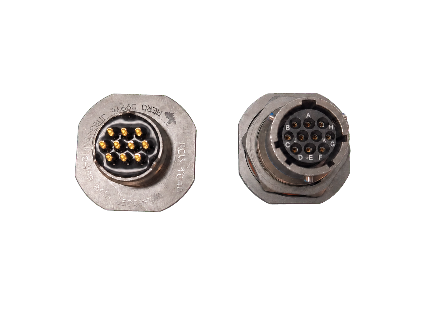 ENGINEERED TO REQUIREMENT
OVERVIEW
RCV supports standard non-filtered connector requirements alongside our filtered product lines. Whether the program needs a PC-tail interface, a conventional termination, or complementary hardware, our focus remains the same: accurate execution and practical lead times.
AEROSPACE & DEFENSE CONNECTORS
RCV supports MIL-DTL-38999, MIL-DTL-26482, MIL-DTL-5015, and MIL-DTL-83723 connector requirements. Share the exact series, connector part number, shell style, insert arrangement, contact type, and keying, together with the drawing and program requirements, to establish the appropriate non-filtered configuration.
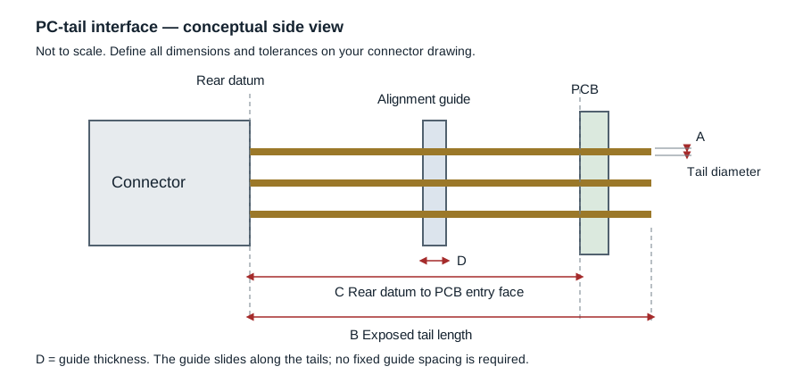
For a D38999 PC-tail connector, the board interface needs its own review. Tail diameter, tail length, PCB hole pattern, board thickness, and connector-to-board spacing must work together. A matching PC-tail alignment disc helps maintain the contact pattern during handling and board installation.
RCV supplies standard non-filtered connector configurations for aerospace, defense, test, and mission-critical electronic systems. Available approaches include MIL circular platforms, pin and socket arrangements, conventional terminations, PC tails for direct printed-circuit-board integration, and complementary backshell hardware.
Programs can source standard and filtered connector requirements through the same responsive engineering team. RCV helps define the shell, contact arrangement, termination, orientation, and supporting hardware needed for the assembly rather than forcing the application into an incomplete configuration.
Explore D38999 alignment discs and PC tail guides →
Send the connector part number or drawing, series, shell size and style, insert arrangement, pin or socket requirements, keying, tail diameter and length, PCB layout, board spacing, quantity, and required delivery date. Include any material, finish, environmental, or qualification requirements for review.
An alignment disc can support the tails and help preserve the board-entry pattern. Its suitability depends on the actual connector, tail dimensions, and assembly geometry; review these together rather than selecting a guide by shell size alone.
RCV supports MIL-DTL-38999, MIL-DTL-26482, MIL-DTL-5015, and MIL-DTL-83723 connector requirements, including pin and socket arrangements, PC-tail and conventional terminations, and supporting hardware. Share the part number and drawing to confirm the configuration for your application.
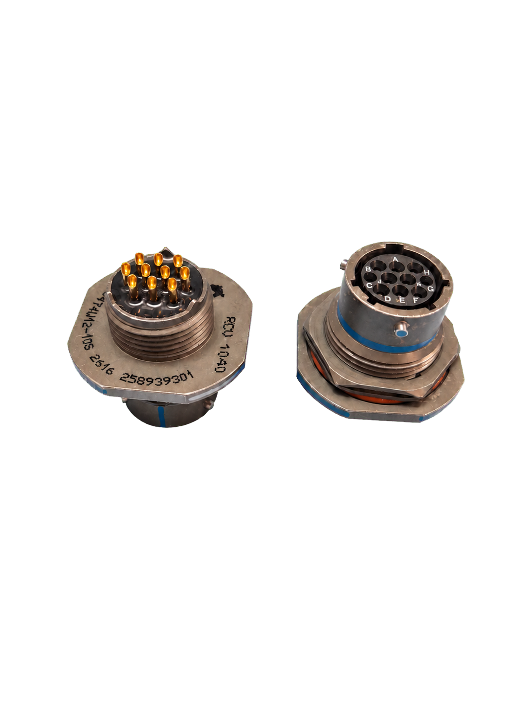
A PC-tail connector uses extended contacts designed to pass directly into a printed circuit board for soldered board-level integration.
Yes. RCV supports standard non-filtered connectors as well as custom filtered connector technologies for programs that need both.
Provide the required receptacle mounting style, shell size, insert arrangement, and pin or socket interface. Include the required contact sizes from 12–22, tail dimensions, and the mating connector or drawing so compatibility can be reviewed.
PRODUCT VIEWS
CONFIGURATION GUIDE
Use this guide to prepare a D38999 or MIL circular PC-tail connector request. Provide the details you know and flag anything that needs engineering review.
Specify MIL-DTL-38999 (D38999), MIL-DTL-26482, MIL-DTL-5015, or MIL-DTL-83723, followed by the exact series and part number when available.
Use a defined connector rear datum and include units and tolerances. Tail length and connector-to-board spacing are separate dimensions.
The alignment guide slides along the PC tails, so customers do not need to specify a fixed guide position or spacing.
Include electrical and environmental requirements, required testing or documentation, prototype and production quantities, and your delivery schedule.
Attach the connector drawing and revision, board interface drawing, and any mating-part information. Missing dimensions can be identified during engineering review.
Send your completed worksheet and drawings to engineering@rcvinterconnect.com, or attach them when sending your RFQ email.
Configure the connector family and board interface together. Provide the exact series and part number so the shell, insert arrangement, contacts, and termination can be reviewed.
Pin and socket options, contact sizes 12–22, and custom tail dimensions allow the connector-to-board interface to be defined around the assembly. Specify receptacle style, tail diameter and length, board thickness, mounting position, and PCB hole pattern.
An alignment disc supports the extended contacts during handling and PCB installation. Match the guide to the actual contact layout and tail geometry.
ENGINEERING SUPPORT