
Planar arrays, Pi tubes, and chip capacitors offer three established approaches to integrating electromagnetic interference (EMI) filtering into connectors. The best choice depends on the required attenuation across frequency, electrical and mechanical constraints, cost, and delivery schedule.
No single approach is best for every application. Begin by identifying the frequencies where emissions exceed the applicable limits and the additional attenuation needed. Then compare connector designs against those requirements while accounting for the signals each contact must carry.
Start With the System Requirement
To recommend a filtered connector, RCV needs to understand the frequencies of concern and the required attenuation. Provide radiated and conducted emissions test results, where available, showing where emissions exceed the applicable limits. Include connector details, signal bandwidth or data rate, operating voltage, current requirements, termination style, environmental conditions, available installation space, and qualification requirements.
How the Technologies Differ
Planar arrays integrate ceramic capacitors around the connector contact pattern and support C or Pi filter configurations. Pi tubes combine tubular capacitive elements with inductive elements. Chip-capacitor designs use discrete surface-mount capacitors on a printed circuit board, allowing capacitance to be selected on a pin-by-pin basis.
Attenuation depends on the complete filter network and its integration. Capacitance, circuit topology, inductive elements, grounding, contact layout, installation, and source and load impedances all influence performance. A properly engineered planar Pi design may be the preferable solution for one design whereas a Pi tube design may better suit another application.
Planar Pi and Pi tube designs provide strong broadband attenuation whereas Chip-capacitor designs can provide effective attenuation over a targeted frequency range typically known as a “Notch Filter”. Surface mount component parasitics, layout, and grounding can limit performance at higher frequencies. Their attenuation may peak near resonance and then decline, so measured performance across the required band is more useful than a peak attenuation figure alone.
Match the Design to the Application
For a significant percentage of applications, the “Notch Filter” solution using surface mount chip-capacitor filtering may offer a practical balance of performance, cost, and delivery time. Higher attenuation requirements across a broader frequencies may favor a planar Pi or Pi tube design. Confirm the choice against the required frequency response and the signals that must pass through the connector.
For the Pi tube options described here, available capacitance is limited to a maximum of approximately 10 – 12 nF. Pi Tube filtering is generally best suited to filtering above about 10 MHz; requirements below this range may favor a planar array which can provide higher capacitances. Chip-capacitor options can address targeted filtering requirements from approximately 1 MHz and above. Confirm the required attenuation across the relevant band for the selected configuration. See Filter performance details below.
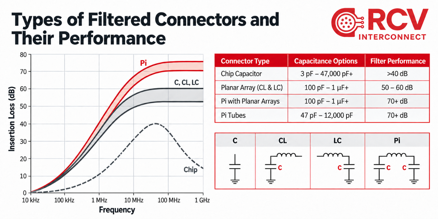
Comparing the Options
Use this comparison to understand the differences between each available option.
| Design factor | Planar array | Pi tube | Chip capacitor |
|---|---|---|---|
| Construction | Ceramic capacitor array integrated around the contact pattern. | Tubular capacitive elements and inductive elements mounted into a ground plane. | Discrete surface-mount capacitors on a custom printed circuit board. |
| Filter configuration | C or Pi configurations with application-specific capacitance. | Pi configuration using available capacitive and inductive elements. | C configurations with capacitance selected on a pin-by-pin basis. |
| Attenuation | Pi planar configurations can support very high attenuation requirements, around 70 dB. | Strong broadband attenuation, with performance up to 70 dB. | Targeted narrowband attenuation up to 45 dB; response may peak near resonance. |
| Frequency range | An option for low-frequency filtering down to the KHz range up into the GHz. | Generally suited to filtering above 10 MHz due to limited capacitance availability. | Targeted filtering from approximately 1 MHz and above. |
| Capacitance | Application-specific values across multiple circuits, including higher capacitance for low-frequency requirements. | Selected capacitance values, up to approximately 10 - 12 nF maximum. | A broad selection of values, with capacitance mixed on a pin-by-pin basis. |
| Voltage | Options for high working voltage and dielectric withstand requirements. | Voltage ratings up to 500 VDC, with dielectric withstand rating of 750 V. | Voltage ratings up to 500 VDC, depending on contact density and configuration. |
| Packaging | Compact construction suited to high contact counts and dense patterns. | Fit depends on element size and contact arrangement; some designs may require a longer connector body or potting extension. | Compact construction; board layout and grounding affect fit and performance. |
| Electrical considerations | Confirm available capacitance, voltage ratings, and frequency response. | Confirm available tube values, voltage ratings, and attenuation at the frequencies of concern. | Confirm attenuation across the required band, voltage ratings, and effects on desired signals. |
| Relative cost | Typically higher; custom arrays may involve minimum order quantities. Very cost effective in higher volumes. | Depends on contact count and construction; cost can rise with larger pin counts. | Lower cost with flexibility in component selection. |
| Delivery considerations | Custom array lead times can drive the schedule. | RCV stocks several Pi tube values, which may support shorter delivery times than custom planar arrays. | Typically the shortest lead time when surface-mount capacitors are readily available through distribution. |
| Typical selection drivers | Dense contact layouts, higher capacitance requirement, higher voltage requirements, and large production volumes. | Broadband attenuation and typically shorter delivery lead times. | Targeted attenuation, mixed capacitance values, cost, and delivery requirements. |
Next Step
Contact RCV Engineering at engineering@rcvinterconnect.com to discuss your specific application. RCV provides 30+ years of expertise in EMI filtering and we work hand in hand with your engineering team to develop the best possible solution for your application.