
Press-In EMI Filters: Add EMI/RFI Filtering Without Redesigning Your Connector
Electromagnetic interference can become a significant problem late in the development of an electronic system. A design may function properly in the lab, only to encounter EMI/RFI issues during system integration, qualification testing, or EMC compliance testing.
At that point, redesigning a circuit board or replacing an existing connector with a completely new filtered connector can add cost, complexity, and time to a program.
Press-In EMI Filters provide another option.
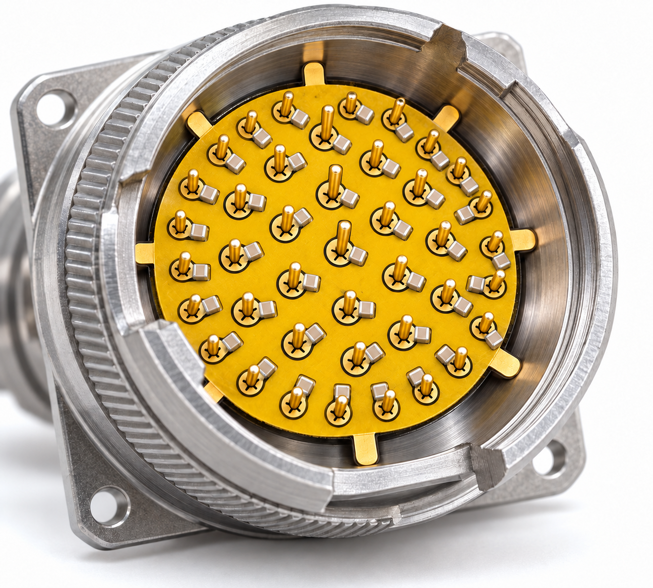
RCV Interconnect Press-In Filters are designed to add connector-level filtering directly to an existing connector using a flexible circuit populated with discrete filter components. The filter presses in on the pin contacts of the connector, allowing engineers to introduce EMI suppression at the equipment interface without requiring a major redesign of the connector or system.
For applications where size, schedule, and system changes must be minimized, a Press-In Filter can provide an easy way to solve EMI issues.
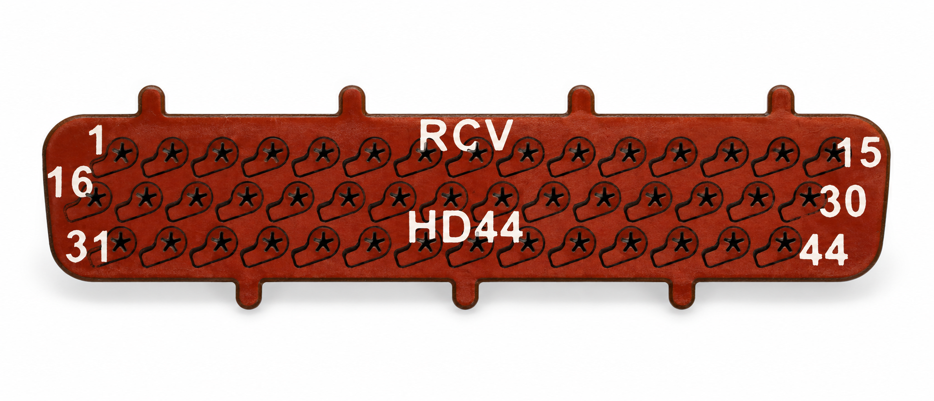
What Is a Press-In EMI Filter?
A Press-In Filter, sometimes called an EMI filter insert, connector filter insert, or flex filter insert, is a filtering assembly installed directly onto the pins of an existing electrical connector.
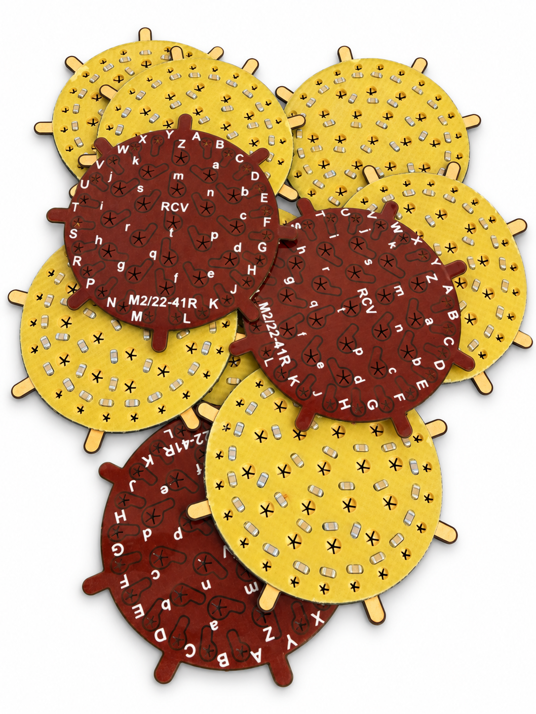
The RCV design is based on a flexible printed circuit populated with surface-mount components such as chip capacitors. Gold-plated contact areas around the contact openings provide the electrical connection to the connector pins, while other gold-plated grounding tabs provide the electrical “discharge” path to the connector shell.
The result is a compact filtering network positioned inside the connector on the pin contacts.
Rather than replacing the existing connector with a dedicated filtered connector, the Press-In Filter allows the standard connector to remain part of the design.
This can be particularly valuable for:
Existing or qualified system designs
EMI problems discovered late in development
Retrofit and upgrade programs
Programs with limited internal space or PCB space
Applications requiring fast prototype or qualification solutions
Designs where changing the connector interface is undesirable
Why Filter EMI at the Connector?
EMI filtering is most effective when unwanted high-frequency energy is controlled as close as possible to the point where signals enter or leave the equipment enclosure. A cable connected to an enclosure can provide a path for conducted interference to enter sensitive electronics or for internally generated noise to leave the system. Filtering directly at the connector interface is the best location to eliminate unwanted high-frequency energy by shunting it to ground before it can radiate into or out of the unit.
For aerospace, defense, industrial, and other high-reliability electronics, connector-level filtering can therefore be an important part of the overall electromagnetic compatibility strategy.
How an RCV Press-In Filter Works
The RCV Press-In Filter provides a decoupling capacitor directly at the unit’s interface to reduce or eliminate the unwanted high-frequency noise that might exist on the incoming or outgoing lines of the connector.
Each filtered contact passes through a plated opening in the flexible circuit. Surface-mount capacitors connect the selected contacts to the filter's ground structure.
At normal operating frequencies, the signal continues through the connector unimpeded.
In higher frequencies above the data frequency, the capacitive coupling shunts the unwanted high-frequency energy to the ground.
The basic capacitive reactance relationship is:
Xc = 1 / (2πfC)
Where:
Xc = capacitive reactance
f = frequency
C = capacitance
This relationship illustrates an important characteristic of capacitive EMI filtering: the selected capacitance directly affects the frequency range over which the filter provides useful attenuation.
A larger capacitance begins shunting noise at a lower frequency, while a smaller capacitance may be preferable on higher-speed or frequency-sensitive signal lines.
This is why EMI filtering should not be approached as a single capacitance value applied indiscriminately to every contact.
Pin-by-Pin Filtering
One of the major advantages of a Press-In Filter is the ability to tailor the filter to the electrical requirements of individual circuits.
A single connector may carry several different types of signals, including:
DC power
Low-frequency control lines
Analog signals
Digital signals
Communication circuits
Ground contacts
Reserved or unused contacts
Those circuits may not require the same capacitance on each pin.
RCV configures the Press-In Filter so that each pin can have its own unique filtering or capacitance. For example, power lines can handle higher capacitance values in order to provide filtering in lower frequencies whereas signal lines can’t handle such large capacitances as it would interfere with the data transmission frequency. Hence, communications and signal lines typically use lower capacitance filtering to eliminate higher frequency noise.
This pin-by-pin approach allows the filtering network to be designed around the system instead of forcing the system to accommodate a uniform filter.
The Importance of Grounding
At higher frequencies, small amounts of inductance in the grounding path can reduce filter performance. For this reason, the mechanical and electrical connection between the Press-In Filter and the connector ground structure is a critical part of the design.
RCV Press-In Filters are made with a single continuous ground plane on the flexible circuit with small isolation channels around each pin contact. The surface mount filter components are mounted across this isolation channel, bridging from the pin contact to the ground plane. Short “grounding tabs” extend from the ground plane providing the electrical path between the Press-In Filter and connector shell. Keeping this path short helps reduce parasitic inductance and allows the filtering components to perform more effectively at higher frequencies.
Successful connector-level EMI filtering depends not only on selecting the correct capacitance, but also on controlling the path from the signal contact through the filter and to the equipment ground. Let our EMI experts at RCV Interconnect help you configure your Press-In Filter design to maximize the performance in your system.